Compression Springs: Engineering Specifications and Selection Guide 2026
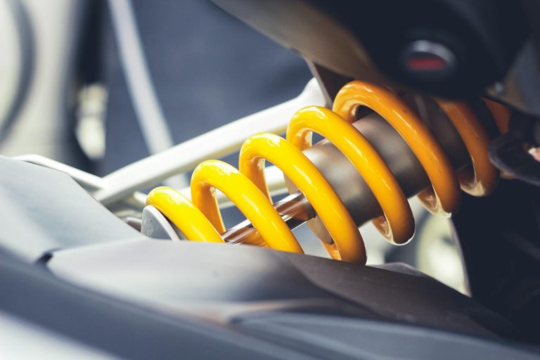
Compression springs are helical mechanical devices engineered to resist axial compressive forces by storing energy as they are compressed. These components serve as the foundation for mechanical control, load distribution, and vibration isolation across automotive, industrial, and furniture applications. Unlike extension springs which pull, compression springs are defined by their ability to provide a predictable, linear resistance to an applied load until the coils make contact, a state known as solid height.
⚡ In a Rush? Key Takeaways
- Spring rate is measured in N/mm and dictates the force required for a 1mm deflection.
- Common materials include Music Wire (ASTM A228) for high-stress cyclic applications.
- Always design for a maximum operating deflection of 80% of the total available stroke.
- Avoid solid height contact to prevent stress concentrations and early fatigue failure.
- ✅ Use our Gas Spring Force Calculator for assist systems.
How Do You Calculate Compression Spring Force and Rate?
Force is calculated using Hooke’s Law where F equals spring rate multiplied by deflection, measured accurately in Newtons and millimeters.
What is the formula for spring rate?
The spring rate is determined by wire diameter, coil diameter, and the number of active coils using the standard torsional spring formula.
The spring rate, or stiffness, is defined by the physical geometry of the spring. It represents how many Newtons of force are required to compress the spring by one millimeter. As an engineer, you must verify these dimensions before finalizing any assembly design.
- G: Shear Modulus of the material
- d: Wire diameter
- D: Mean coil diameter
- Na: Number of active coils
How does deflection affect the working load?
Working load equals the spring rate multiplied by the distance compressed, assuming the spring operates within its elastic linear range.
Total load is cumulative based on the travel distance from free length. If you compress a spring with a 5 N/mm rate by 20mm, the resulting force is 100 Newtons. Exceeding the elastic limit leads to permanent set, where the spring fails to return to free length.
What end types are available and how do they affect performance?
End configuration influences buckling resistance, load distribution, and manufacturing tolerances.
Compression springs can be supplied with plain ends, closed ends, closed and ground ends, or pigtail ends. Closed ends increase the effective number of active coils and provide a flat bearing surface, reducing uneven loading and improving buckling stability. Closed and ground ends further ensure perpendicularity to the spring axis, which is critical for precision applications such as valve springs. Plain ends are the least expensive but can cause tilting under load, increasing the risk of buckling. Selecting the appropriate end type based on the spring’s slenderness ratio and application requirements helps maintain linear force characteristics and prolongs fatigue life.
Which Materials Are Best for Compression Springs?
Material selection is dictated by the operating environment, temperature, and cyclic fatigue requirements of your mechanical assembly.
Why choose music wire for industrial use?
Music wire offers the highest tensile strength and is ideal for high-cycle applications where space and weight are primary constraints.
Music wire (ASTM A228) is the standard for high-performance applications. Its uniform properties ensure consistent force application across millions of cycles. In standard industrial machine guard applications, this is the default material choice.
When should you specify stainless steel?
Stainless steel 302 or 316 provides essential corrosion resistance for marine, food-grade, or outdoor environments in wet conditions.
While stainless steel has a slightly lower shear modulus than carbon steel, its environmental resilience makes it mandatory for marine and outdoor hatch hardware. It resists oxidation far better than zinc-plated music wire in humid UK climates.
What Are the Common Failure Modes for Compression Springs?
Compression springs fail primarily through fatigue, buckling, or stress relaxation caused by operating beyond intended specifications.
How do I identify spring fatigue failure?
Fatigue failure manifests as cracks or fractures at the coil base, typically caused by cyclic loading exceeding the fatigue limit.
Fatigue is the most frequent cause of premature component failure. If your furniture mechanism stops holding weight, inspect the coils for hairline fractures. Frequent contact with solid height drastically accelerates this degradation.
How do I prevent spring buckling?
Buckling occurs when the free length to mean diameter ratio is too high, requiring a rod or tube guide to ensure stability.
If your spring length exceeds four times the mean coil diameter, the spring is prone to bowing under load. Always specify a guiding rod or internal sleeve if the application allows for it. This simple addition prevents the spring from shearing against internal housing walls.
FAQ: Compression Spring Sizing
Common questions regarding compression spring selection, maintenance, and design optimization for high-performance mechanical engineering.
Can I cut a compression spring to fit?
Cutting a compression spring increases the spring rate and destroys the end coil geometry, causing uneven force distribution.
How is solid height determined?
Solid height is the product of total coils and wire diameter, representing the state where all coils are fully compressed and touching.
Are compression springs interchangeable with gas springs?
No, gas springs provide a controlled, constant-force assist while compression springs provide linear mechanical resistance and force.
Designing with compression springs requires strict adherence to geometry and material limits. For assistance with load-bearing assemblies, ensure you verify your total deflection requirements against the spring’s rated elastic limit.